
I don't know that much about electronics, but what I want is a relay switch that can handle 2V to turn on a circuit that handles 5V.
I want something to happen when the Green light of the Eject button the XBOX is activated.
I'm not sure what to look for in a relay that will with those specs and do I need anything else to make it work? From what I've read a SSR would be nice, because then I wouldn't get that 'click' sound.
Thanks in advanced!
Relay switch question.
-
Nextelhalo

- Posts: 725
- Joined: Wed Jul 04, 2012 5:55 am
- Location: Yoyorast Island
- Has thanked: 61 times
- Been thanked: 77 times
Re: Relay switch question.
What exactly are you trying to accomplish here? I'm no electrical expert either but I bet between Prof. Johnny and Xman we could help you with what your trying to do.
Halo LE Blue (Japan Black jewel) v1.0 1.0GHZ Trusty 128 RAM 640GB Blue-White P/E LED's
White v1.4 X3 CE with X3 CP 500GB Blue-white P/E LED's Blue Jewel
Debug kit untouched
White v1.4 X3 CE with X3 CP 500GB Blue-white P/E LED's Blue Jewel
Debug kit untouched
Re: Relay switch question.
I have a SmartXX v2 chip on a v1.4 motherboard, that I've hooked up to a LCD data screen.
The LCD screen needs 5V to operate and 5V for the backlight.
I've had to run an alt point of 5V to the modchip because it's not pulling enough otherwise from the pin header.
This still isn't enough for the backlight. So I'm using one of the USBs to power it. Which means that the backlight is on all the time.
If I could use a relay switch, hooked up to the LED green power, it would mean that when loading something I could have the green power turn off, which would also mean the backlight would turn off as well.
-
Nextelhalo
- Posts: 725
- Joined: Wed Jul 04, 2012 5:55 am
- Location: Yoyorast Island
- Has thanked: 61 times
- Been thanked: 77 times
Re: Relay switch question.
The 5V from the USB shouldnt always be on, atleast I dont think. I thought it received power once the switch was hit. Either way there could be a 5v line on the bottom of the board somewhere you could use.
Halo LE Blue (Japan Black jewel) v1.0 1.0GHZ Trusty 128 RAM 640GB Blue-White P/E LED's
White v1.4 X3 CE with X3 CP 500GB Blue-white P/E LED's Blue Jewel
Debug kit untouched
White v1.4 X3 CE with X3 CP 500GB Blue-white P/E LED's Blue Jewel
Debug kit untouched
-
professor_jonny

- Posts: 1298
- Joined: Thu Jul 05, 2012 5:41 am
- Location: New Zealand
- Has thanked: 66 times
- Been thanked: 196 times
Re: Relay switch question.
you wont find a 2v relay well i have never seen one and also as they have a coil in them they can let off an inductive spike and dammage things.
if it were me i would use a small n channel fet or transistor.
the usb is not powered all the time but it would be better to drag a 5v line from the power supply that is only powered when running ?
possibly the 5v line to your chip is powered all the time making the backlight stay on ?
if you want to control the lcd with the led output you would need a transistor or fet an ssr is way out of the price range probally cost more than 10 xboxes and they are usually 4 to 8v 24v or 240v
Re: Relay switch question.
I guess I didn't explain myself correctly enough.
You see in XBMC4XBOX there is an option of LCD under smartxx to control contrast and the backlight, but neither of these work for me, even though I have a SMARTXX v2 and a HD44780 compatible LCD.
When I said, always on for powering the backlight, I meant only when the xbox has be turned on. XBMC4XBOX has different options to turn the ring off/green/red/orange/flash/cycle/etc at different times. I'd like the backlight to turn off when the ring is off. The LCD is powered by the modchip, which in turn is pulling 5V from an alt sauce than the pin header.

The backlight is powered directly from port3 USB.
I'd thought of a relay switch because I'd seen mods for when people put their IR dongles inside their XBOX.
After looking around, I was kinda hoping something like this would work? In line with a resistor of some sort?
http://uk.mouser.com/ProductDetail/Pana ... 5HfFH8k%3d
You see in XBMC4XBOX there is an option of LCD under smartxx to control contrast and the backlight, but neither of these work for me, even though I have a SMARTXX v2 and a HD44780 compatible LCD.
When I said, always on for powering the backlight, I meant only when the xbox has be turned on. XBMC4XBOX has different options to turn the ring off/green/red/orange/flash/cycle/etc at different times. I'd like the backlight to turn off when the ring is off. The LCD is powered by the modchip, which in turn is pulling 5V from an alt sauce than the pin header.
The backlight is powered directly from port3 USB.
I'd thought of a relay switch because I'd seen mods for when people put their IR dongles inside their XBOX.
After looking around, I was kinda hoping something like this would work? In line with a resistor of some sort?
http://uk.mouser.com/ProductDetail/Pana ... 5HfFH8k%3d
-
xman

- Posts: 1289
- Joined: Wed Jul 04, 2012 2:30 pm
- Location: Sydney, Australia
- Has thanked: 55 times
- Been thanked: 168 times
Re: Relay switch question.
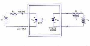
I'd use an opto coupler. The relay coil is replaced by an LED, ( a red LED so the required voltage is only 1.2vDC), and it in turn, when turned on , shines onto a photo transistor that connects the output terminals. This is the theory of there operation so you have a basic understanding of how the hell they actually work.  All this is inside a 6 pin chip so no moving parts. Here's a pic to give you a few ideas.
Alternatively, you could use a Darlington array like this one. Over kill because it has 7 circuits inside and you only need one but these things are cheap anyway...
http://pdf.datasheetcatalog.com/datashe ... 337_DS.pdf.
I could suggest a simple transistor but P.J. has already mentioned that so no need for me to go over that.
Re: Relay switch question.
I really appreciate the help from everyone!
If a simple transistor would do the job, I'm happy to use that. But even that I'm a little lost on. And I'm more than happy to do some background reading, I just don't want to end up buying the wrong thing, and blow everything. I've had my XBOX and modchip for over 10 years, which I fitted myself. It's only in the past year I've started opening the XBOX up again and doing some 'fancy' mods to it.
This opto coupler, (apart from sounding like something from a B-movie) I'd never heard of before. I'll go hunting on ebay.co.uk for one. Sadly where I live there is no electric component stores and those type of online stores want an arm and a leg just for postage.
Thanks again for the help!
-
xman
- Posts: 1289
- Joined: Wed Jul 04, 2012 2:30 pm
- Location: Sydney, Australia
- Has thanked: 55 times
- Been thanked: 168 times
Re: Relay switch question.
Yep, I understand where your coming from. Optos are good in the respect that they "optically isolate", circuits meaning if something goes tragically wrong with one of the circuits, it is physically impossible for the fault to blow the other circuit because it is light activated so no connecting wires and electricity can't travel through light, yet. I'm presuming you want one of the selected ring LED colours to control the display back-light?. If this is true you will need to access the ring colour LED supply, ( available on the front switch panel), and use this to power the opto LED wire, transistor base or what ever else you choose to drive the circuit. I would personally have the back-light + connected to any of the available +5vDC sources and use the device be it a transistor or opto coupler to switch the ground wire of the back-light. Really need to know how much current your display requires in it's back-light circuit. I'm suspecting only 10-20mA as most only use a LED to do the back-lighting of displays. This leads me to mention , if you are prepared to alter the existing resistor on the front board itself that is used to drive the ring LED colour you choose, you could actually power the display back-light, in series with the actual ring LED, meaning no external switching device at all would be required. It would work to some extent just wiring the back-light in series as is however the back-light and the ring colour will be very dull thus the need to alter the existing resistor that is only valued to supply enough current to drive one LED and not two.
Re: Relay switch question.
The LCD's datasheet is as follows...
http://www.blandongroup.com/datasheets/ ... 50dpi).pdf It's the Wide temp, 4x20 one.
I've had a look at the front panel PCB and there only seems to be two LEDs and two push buttons switches. If there is a resistor on the motherboard, then no, my soldering skills don't go that far, I don't think.
I'm still looking for an opto
-
xman
- Posts: 1289
- Joined: Wed Jul 04, 2012 2:30 pm
- Location: Sydney, Australia
- Has thanked: 55 times
- Been thanked: 168 times
Re: Relay switch question.
Mother board, not what you really want to mod, I understand. Here's the opto I had in mind.

Any in the 4N series should do the job. All are similar to this one. This one being a 4N25. There is also the 4N26, 27, 28 etc. To use this in you application, you would simply remove your LED circle wire and solder it to pin A, connect pin C to the ground of the LED circle, (it's common to all the LEDs and switches on the board). This will have the LED inside the opto powered instead of the circle LED coming on. Your switch will be between C and E. Power it on and you have a connection between C and E, turn it off and there is no connection..
Any in the 4N series should do the job. All are similar to this one. This one being a 4N25. There is also the 4N26, 27, 28 etc. To use this in you application, you would simply remove your LED circle wire and solder it to pin A, connect pin C to the ground of the LED circle, (it's common to all the LEDs and switches on the board). This will have the LED inside the opto powered instead of the circle LED coming on. Your switch will be between C and E. Power it on and you have a connection between C and E, turn it off and there is no connection..
Re: Relay switch question.
Thanks!!!
I've managed to get 5 of 4N25 for a few quid. A lot cheaper than I thought they might be. I should have them sometime next week.
I'll let you know how I get on!
I've managed to get 5 of 4N25 for a few quid. A lot cheaper than I thought they might be. I should have them sometime next week.
I'll let you know how I get on!
Re: Relay switch question.
Well I've soldered a 4N25 in, and I've got it working, but the LCD isn't any where near as bright as if I hook it up directly. It seems it's not getting enough juice.
-
professor_jonny
- Posts: 1298
- Joined: Thu Jul 05, 2012 5:41 am
- Location: New Zealand
- Has thanked: 66 times
- Been thanked: 196 times
Re: Relay switch question.
you could use the opto isolator to drive a fet or transistor or relay now
your opto could be at a state of half on as there is not enough power flowing in the primary you could try change your current limiting resistor to the led module on the xbox, as you now effectivly have 2 led's in paralell halving the current.
If you use a fet what you would do is connect the collector to 5v then use the emitter to drive the gate pin of the fet.
then you would have to connect a resistor to ground from the gate to ensure it turns off as there may be bleed voltage in the opto.
-
xman
- Posts: 1289
- Joined: Wed Jul 04, 2012 2:30 pm
- Location: Sydney, Australia
- Has thanked: 55 times
- Been thanked: 168 times
Re: Relay switch question.
You could trace the LED in the circle supply back to it's dropping resistor on the mother board and attach your opto LED supply to the power side of that resistor rather than the circle LED side of it. This way it will be at full logic voltage rather than the dropped down voltage designed to run just the circle LED. You will then need to use a dropping resistor to drop that logic voltage down to a suitable voltage to the opto LED, ( so you don't cook it by driving the LED with full logic voltage), but this will have the opto fully driving on and no need to alter the factory resistor. Now to actually drive the display backlite you would have the display's backlite "+" supplied direct from a 5vDC supply on the machine. You would have the "-" wire from the display backlite connected to the "C" terminal on the opto's chip, (pin 5 I think it is). And "E" or pin 6 on the chip , you would connect it to any earth or ground available on the Xbox. To confirm it is hooked up correctly, simply short out the pin 5 and pin 6 with a wire and the backlite should light up. This is solely to test the output side of the circuit.