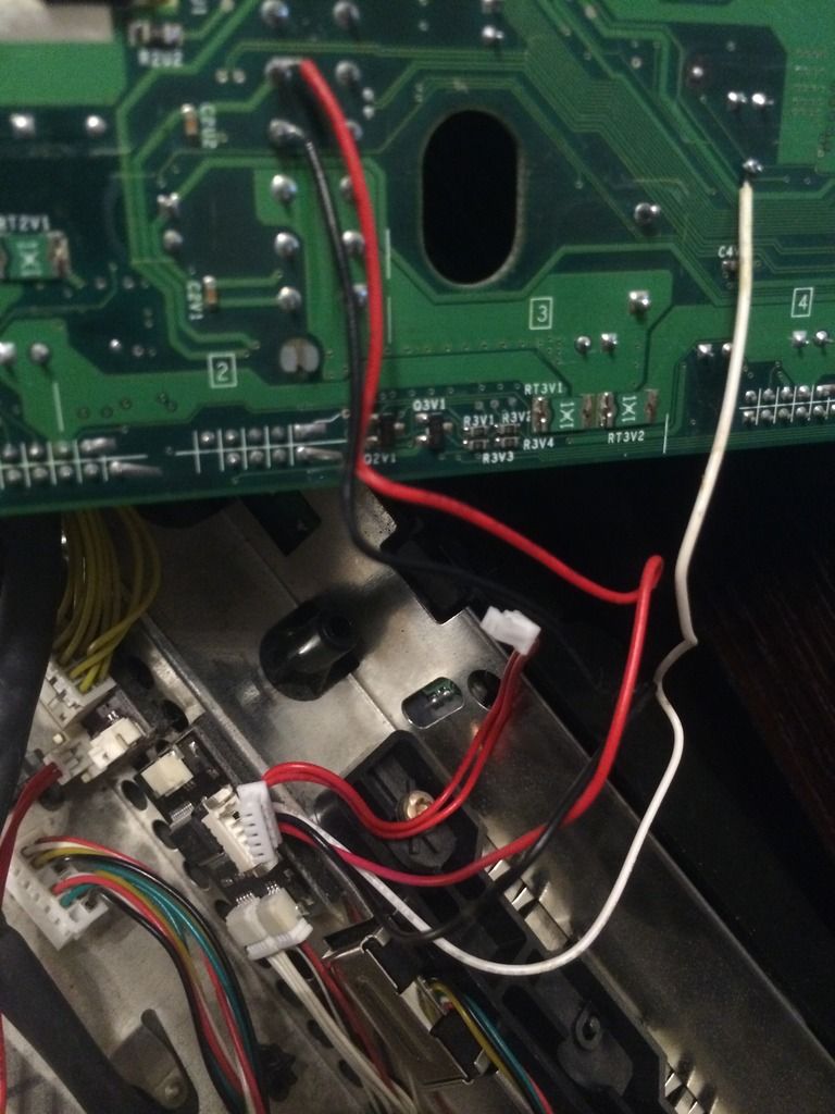
These three wires join two red wires to create a connector which inserts into the switch board. The two red wires are not free ended like the three coming from the power connections. It has a connector and goes into the lcd board.
Image below

If anyone knows or has the diagram from team executers install guide (which is no longer online - i tried accessing it with wayback machine archives, but it requires a log in to view hence wont be viewable using the archives).
Hope someone knows which point i should solder it back on.....
Thanks in advance.
