
https://www.kickstarter.com/projects/pi ... aspberry-p
Building Picade (mini arcade cabinet)
-
BuZz

- Site Admin
- Posts: 1891
- Joined: Wed Jul 04, 2012 12:50 am
- Location: UK
- Has thanked: 66 times
- Been thanked: 423 times
- Contact:
Building Picade (mini arcade cabinet)
Got one of these in the post yesterday. Started building it today (comes in kit form)
https://www.kickstarter.com/projects/pi ... aspberry-p
Since pics taken the back door, and speakers are in. Currently assembling the main controls. More spam pics soon.
https://www.kickstarter.com/projects/pi ... aspberry-p
Since pics taken the back door, and speakers are in. Currently assembling the main controls. More spam pics soon.
-
xman

- Posts: 1289
- Joined: Wed Jul 04, 2012 2:30 pm
- Location: Sydney, Australia
- Has thanked: 55 times
- Been thanked: 168 times
Re: Building Picade (mini arcade cabinet)
Sweet. I hope to see lots of pics now BuZz. You need to sort the power out on this project you were saying on TeamSpeak, Now I have somewhere to post some pictures of the various designs that may interest you as well as the many pre made power supplies I have seen that you could use for your project.
-
BuZz
- Site Admin
- Posts: 1891
- Joined: Wed Jul 04, 2012 12:50 am
- Location: UK
- Has thanked: 66 times
- Been thanked: 423 times
- Contact:
Re: Building Picade (mini arcade cabinet)
Thanks xman. There are a few options I guess including PSU with both 12v+5v, or using a better 12v PSU and having some converter board etc. I guess I'd like a powered hub inside for peripherals too. Currently the situation is:
12v 1a psu for screen (comes with picade)
Picade board (input controller / audio amplifier ) - which is powered via USBfrom the Pi or another device
Then I have a Pi, powered from a separate PSU.
In the Picade model I have, the controller board for the display also has an amplifier built in, and it can split the audio out from the HDMI which is handy.
Here's a continuation of pics. Currently I've just powered everything up to test, and am checking button wiring etc.
-
BuZz
- Site Admin
- Posts: 1891
- Joined: Wed Jul 04, 2012 12:50 am
- Location: UK
- Has thanked: 66 times
- Been thanked: 423 times
- Contact:
Re: Building Picade (mini arcade cabinet)
Here is an interesting blog detailing a build.
http://jonthysell.com/2014/01/12/buildi ... ni-part-i/
and this from kickstarter comments
http://jonthysell.com/2014/01/12/buildi ... ni-part-i/
and this from kickstarter comments
This will only work with the Maxi Screen Driver board. M.NT68676.2A
Spec here:- http://www.drivestar.biz/files/M.NT68676.2A.pdf
Do not attempt this unless you are very proficient at soldering and have good electronic knowledge.
The speakers are the most straight forward.
Looking from the front of the board, ie the side with all the monitor connectors and power connectors on it; on the right hand side there is a 4 pin white connector, labelled
CN20. Running from front to back it is R speaker out, Ground, Ground, L speaker out (labelled on the back of the board, RO, GND, GND, LO). Either find a plug that will plug
onto that connector, or solder directly on to the back of the board, to your speakers, make sure there are no short circuits? make sure there are no solder bridges? Then you can either set the Pi to output audio over HDMI, or, use the audio cable you
were supplied with to plug into the second plug from the right, on the front of the board, which is an audio in socket. Then simply by using the OSD Up - Down arrow buttons
you can change the volume.
If you had any problems doing the speaker mod. above, do not attempt this further mod. as you will damage your Pi and the screen driver board.
Powering your pi from the screen driver board.
You may need a higher current 12V supply, than the one originally supplied, which was 1Amp; a 2Amp would be ample, depending on what you are powering, I've tested the
5V output up to 1.5A, which is plenty to drive a Pi and small hub a WiFi dongle and mouse and keyboard.
This will only work with the Maxi Screen Driver board. M.NT68676.2A
Spec here:- http://www.drivestar.biz/files/M.NT68676.2A.pdf
Looking from the front of the board, ie the side with all the monitor connectors and power connectors on it; on the left hand side of the board behind the connector that goes to
the LCD labelled 'CN5 INVERTER', there are 6 vacant pin holes in a line, labelled CN3. These are, from front to back Power On, 5V standby, 5V power, 5V power, Ground,
Ground. (labelled on the back of the board PON, 5VSTB, +5V, +5V, GND, GND) We are only interested in the +5V and GND connections. You will need to suck the solder
out of these 4 holes and then make up two short loops of copper wire in the shape of a long U, solder one of these into the holes for each pair of +5V and GND connections,
ie so the two +5V are connected together and so the two GND are connected together. Then make up a cable, from some multi-strand wire, not bell wire it's too thin and
connect to the P1 connector on the Pi, detailed information here:-
http://elinux.org/RPi_Low-level_periphe ... .28GPIO.29
You need to connect the +5V to pin 02 of P1 and the GND to pin 06 of P1, by doing this you will be bypassing the poly fuse on the Pi as well, so take care. I used a 3 pin
plug that came of an old PC fan, this was the correct pitch and fitted over pins 02, 04 and 06, you may need to trim some of the plastic off the plug so it does not bind with
other pins, I only connected to 02 and 06, the other end of the cable I soldered to the copper loops that I had inserted into the +5V and GND connections on the display driver
board so +5V goes to P1 pin 02 and GND goes to P1 pin 06.
Double check what you have done, is the polarity correct? check with a multi-meter, that there are no short circuits? check for any solder bridges?
Firstly with the pi disconnected, power up the display driver board and check that there is 5V on the connector and it's the correct way round? power off the display driver
board. If all is good, then connect the Pi to your new connector, check you've got it on the correct pins? then power up the display driver board, the Pi will now also be
powered. If you are only powering the screen and a Pi, I suspect that the 12V 1A supply supplied with your Picade will be adequate, it's what I'm doing and my Pi has a nice
stable 5.0V supply, if you want more power you'll probably need to upgrade the 12V supply to say 1.5A or 2A, remember after upgrading your 12V supply, you can only take
a maximum of 1.5A from the 5V supply on the display driver board, so don't try to power lots of stuff!
Good luck.
Regards, Kevin.
-
BuZz
- Site Admin
- Posts: 1891
- Joined: Wed Jul 04, 2012 12:50 am
- Location: UK
- Has thanked: 66 times
- Been thanked: 423 times
- Contact:
Re: Building Picade (mini arcade cabinet)
In regards to power, I may opt for something simpler than using the controller board as detailed above, although I'm likely to connect the speakers to it, rather than the picade board so I have hardware volume control, and get the audio directly from HDMI.
Something like this http://www.ebay.co.uk/itm/301017584148 (I might spend a little more than £1.40 though ) would suffice to power the screen and the Pi at least.
Something like this http://www.ebay.co.uk/itm/301017584148 (I might spend a little more than £1.40 though
-
Dom DXecutioner

- Posts: 587
- Joined: Thu Jul 05, 2012 11:59 pm
- Location: California
- Has thanked: 249 times
- Been thanked: 226 times
- Contact:
Re: Building Picade (mini arcade cabinet)
gay! 
just kidding slick... pretty cool! now only if you had the time to fix the themoviedb cast scraper... just saying!
just kidding slick... pretty cool!

-
BuZz
- Site Admin
- Posts: 1891
- Joined: Wed Jul 04, 2012 12:50 am
- Location: UK
- Has thanked: 66 times
- Been thanked: 423 times
- Contact:
Re: Building Picade (mini arcade cabinet)
lol - fixing scrapers. that's hardly as much fun 
Picade is all together now. I wired the speakers to the display board (bit fiddly, and not a solder job I am proud of, but works), as the Picade audio out was very noisy as it seems a better idea to take the audio from the HDMI.
Just need to get an emulation package on a card now, so I can play a few games on it before bed
I'll post some more pics tomorrow.
-
xman
- Posts: 1289
- Joined: Wed Jul 04, 2012 2:30 pm
- Location: Sydney, Australia
- Has thanked: 55 times
- Been thanked: 168 times
Re: Building Picade (mini arcade cabinet)
I'm thinking something like this to power it....
http://www.ebay.com/itm/Double-Output-D ... 3777?rt=nc

6 amp @ 5vDc regulated and 2 amp @ 12vDC regulated however a bit more on the 12volt side would be nicer insurance. You'll find one with higher 12 volts regulated real easy. They're everywhere on the net. Just have a look. or maybe..
The beauty of this design power supply is it's simplicity even for the stupidest in society. The screw terminals allow for standard wire lugs found anywhere that can be crimped on the ends of wires. The lugs like these are ideal...

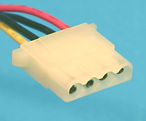
Now if you were to go to your local PC repair guy and ask for a couple of "dead" P.C. power supplies, he will gladly give them to you saving him dumping fees on them, and grab the wiring and connectors all PC power supplies have, you know, 4 pin red, black, black, yellow and then you have connectors as well as being colour coded, red is 5 volt, yellow is 12 volts black is ground. The connectors like these are the ones I use most and are on most old, dead PSs..
Using the wires and connectors from old PC power supplies should give a very nice, professional finish to your project's wiring needs as well as being relatively safe and fire free but that really depends on the operator I guess...
There are millions of ways to power your project but these are simple and reliable and any software fool should be safe working with these...
I've told you of my local P.C. guy saving old , dead power supplies for me in the past. An absolute wealth of wiring, connectors and parts and all for free other than you needing to get rid of the rubbish you don't use. These same style "caged" power supplies are the ones we use in the proper arcade machines for powering the peripheral boards that plug into the P.C.s. These peripherals are things like I/O boards, USB to gun driver boards etc. They offer cheap, reliable sources of regulated power.
Now to hook one of these up. Look at the screw terminals at the end of the power supply...
Going from left to right on the screw terminals.....
1- mains from wall plug lead
2- other mains from wall plug lead
3- ground from wall plug lead
4- black wire that pairs to the yellow 12vDc wire
5- yellow wire (12vDC)
6- black wire that pairs with the red 5vDC wire
7- red wire (5vDC)
Now right beside the end of the connector you have just connected the wires to you will see a little adjuster, (a pot). This is your manual 5vDC adjustment knob. This will come in real handy should you be overclocking your RPi and as a result, your 5vDc is dropping slightly because of the extra power drawn by overclocking. If your confident, ( and have a small jeweler's screwdriver and haven't been drinking excessive amounts of alcohol) , you can put your volt meter in and measure the 5vDC, ( one lead in red and the other in the black beside the red) and turn this knob or pot clockwise and adjust your 5vDc level to precisely what voltage you want. Magic aye. Don't go any higher than 5.20vDC on the Rpi and make sure the RPi is powered up and running while you do this check. You want to set the voltage when the load is on it. This last step of adjusting the 5vDc isn't absolutely necessary because the power supply will be real close to dead on 5vDC anyway but this will enable you to get the most out of your overclocked RPi.
http://www.ebay.com/itm/Double-Output-D ... 3777?rt=nc
6 amp @ 5vDc regulated and 2 amp @ 12vDC regulated however a bit more on the 12volt side would be nicer insurance. You'll find one with higher 12 volts regulated real easy. They're everywhere on the net. Just have a look.
The beauty of this design power supply is it's simplicity even for the stupidest in society. The screw terminals allow for standard wire lugs found anywhere that can be crimped on the ends of wires. The lugs like these are ideal...
Now if you were to go to your local PC repair guy and ask for a couple of "dead" P.C. power supplies, he will gladly give them to you saving him dumping fees on them, and grab the wiring and connectors all PC power supplies have, you know, 4 pin red, black, black, yellow and then you have connectors as well as being colour coded, red is 5 volt, yellow is 12 volts black is ground.
Using the wires and connectors from old PC power supplies should give a very nice, professional finish to your project's wiring needs as well as being relatively safe and fire free but that really depends on the operator I guess...
There are millions of ways to power your project but these are simple and reliable and any software fool should be safe working with these...
I've told you of my local P.C. guy saving old , dead power supplies for me in the past. An absolute wealth of wiring, connectors and parts and all for free other than you needing to get rid of the rubbish you don't use. These same style "caged" power supplies are the ones we use in the proper arcade machines for powering the peripheral boards that plug into the P.C.s. These peripherals are things like I/O boards, USB to gun driver boards etc. They offer cheap, reliable sources of regulated power.
Now to hook one of these up. Look at the screw terminals at the end of the power supply...
Going from left to right on the screw terminals.....
1- mains from wall plug lead
2- other mains from wall plug lead
3- ground from wall plug lead
4- black wire that pairs to the yellow 12vDc wire
5- yellow wire (12vDC)
6- black wire that pairs with the red 5vDC wire
7- red wire (5vDC)
Now right beside the end of the connector you have just connected the wires to you will see a little adjuster, (a pot). This is your manual 5vDC adjustment knob. This will come in real handy should you be overclocking your RPi and as a result, your 5vDc is dropping slightly because of the extra power drawn by overclocking. If your confident, ( and have a small jeweler's screwdriver and haven't been drinking excessive amounts of alcohol) , you can put your volt meter in and measure the 5vDC, ( one lead in red and the other in the black beside the red) and turn this knob or pot clockwise and adjust your 5vDc level to precisely what voltage you want. Magic aye. Don't go any higher than 5.20vDC on the Rpi and make sure the RPi is powered up and running while you do this check. You want to set the voltage when the load is on it. This last step of adjusting the 5vDc isn't absolutely necessary because the power supply will be real close to dead on 5vDC anyway but this will enable you to get the most out of your overclocked RPi.
-
BuZz
- Site Admin
- Posts: 1891
- Joined: Wed Jul 04, 2012 12:50 am
- Location: UK
- Has thanked: 66 times
- Been thanked: 423 times
- Contact:
Re: Building Picade (mini arcade cabinet)
Thanks xman. That looks like an excellent solution. I like the fact the 5v is adjustable too. Just have to make sure I power off the mains before go inside the picade if I use one of these so I don't zap myself on the mains in
I'm tempting to start messing around with the software side of this too, but I had better get xbmc4xbox 3.5 out first
I'm tempting to start messing around with the software side of this too, but I had better get xbmc4xbox 3.5 out first
-
BuZz
- Site Admin
- Posts: 1891
- Joined: Wed Jul 04, 2012 12:50 am
- Location: UK
- Has thanked: 66 times
- Been thanked: 423 times
- Contact:
Re: Building Picade (mini arcade cabinet)
Completed - Minus optimising the power supply as discussed.
-
destronger

- Posts: 36
- Joined: Wed Jul 04, 2012 2:16 am
- Location: Maui... or so I think.
- Has thanked: 5 times
- Been thanked: 6 times
Re: Building Picade (mini arcade cabinet)
that was easy. much easier than building one from scratch like I did. wish I'd done what you did. It'd save me a lot of headaches... and it's still not done. 
when it comes to the electrical why put a non-static silicon over those areas if you feel you might get zapped. or do what I do when dealing with a hot circuit. cover it with elec tape. better safe than sorry. of course you do this before it has power.
when it comes to the electrical why put a non-static silicon over those areas if you feel you might get zapped. or do what I do when dealing with a hot circuit. cover it with elec tape. better safe than sorry. of course you do this before it has power.
+ T +: Every time you mention Midway games in Final Burn, iq_132 kills a kitten!


-
nidge

- Posts: 472
- Joined: Fri Jul 27, 2012 8:29 pm
- Location: Norfolk, United Kingdom
- Has thanked: 24 times
- Been thanked: 26 times
- Contact:
Re: Building Picade (mini arcade cabinet)
Hi Buzz,
Let me know if you want a PC power supply, I've one or two of them going spare AT and ATX.
Let me know if you want a PC power supply, I've one or two of them going spare
http://www.theoriginalxboxshoppe.weebly.com
http://www.ebid.net/uk/stores/Computers-and-Consoles
Crystal Xbox v1.4, Xecuter 3, 500gb sata hard disk, 1ghz CPU, 128mb RAM, HD component 720p, blue LED's.
Crystal Xbox v1.4, Xecuter 3, 320gb sata hard disk, stock CPU, 128mb RAM, HD component 720p.
http://www.ebid.net/uk/stores/Computers-and-Consoles
Crystal Xbox v1.4, Xecuter 3, 500gb sata hard disk, 1ghz CPU, 128mb RAM, HD component 720p, blue LED's.
Crystal Xbox v1.4, Xecuter 3, 320gb sata hard disk, stock CPU, 128mb RAM, HD component 720p.
-
spicemuseum

- Posts: 906
- Joined: Mon Jul 09, 2012 11:08 pm
- Has thanked: 94 times
- Been thanked: 75 times
Re: Building Picade (mini arcade cabinet)
Way cool! What's your view on build quality ... and VFM?
BTW, I got 120,000 on Bomb Jack a few weeks ago. A feat I've been completely unable to repeat, or even get close to again.
BTW, I got 120,000 on Bomb Jack a few weeks ago. A feat I've been completely unable to repeat, or even get close to again.
-
professor_jonny
- Posts: 1298
- Joined: Thu Jul 05, 2012 5:41 am
- Location: New Zealand
- Has thanked: 66 times
- Been thanked: 196 times
Re: Building Picade (mini arcade cabinet)
That would be cool to put on my desk at work when the boss is out
-
BuZz
- Site Admin
- Posts: 1891
- Joined: Wed Jul 04, 2012 12:50 am
- Location: UK
- Has thanked: 66 times
- Been thanked: 423 times
- Contact:
Re: Building Picade (mini arcade cabinet)
Good point.destronger wrote: when it comes to the electrical why put a non-static silicon over those areas if you feel you might get zapped. or do what I do when dealing with a hot circuit. cover it with elec tape. better safe than sorry. of course you do this before it has power.
I'm thinking now I might go for something like a pico PSU, or even something a bit larger in case I want to use something other than a Pi in it in the future.
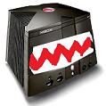
this was on Facebook Picade group from another user.
https://scontent-a.xx.fbcdn.net/hphotos ... 6658_o.jpg
-
BuZz
- Site Admin
- Posts: 1891
- Joined: Wed Jul 04, 2012 12:50 am
- Location: UK
- Has thanked: 66 times
- Been thanked: 423 times
- Contact:
Re: Building Picade (mini arcade cabinet)
thanksnidge wrote:Hi Buzz,
Let me know if you want a PC power supply, I've one or two of them going spare
-
BuZz
- Site Admin
- Posts: 1891
- Joined: Wed Jul 04, 2012 12:50 am
- Location: UK
- Has thanked: 66 times
- Been thanked: 423 times
- Contact:
Re: Building Picade (mini arcade cabinet)
Build quality is excellent. Wooden panels with a power coating giving a lovely finish. Screen is excellent (I waited for availability of 4:3 panel due to issues getting hold of them - they finally found some and they are decent) . Joystick is hefty and good quality. It felt like a lot of care and attention had been put into the kit, and they even included a nice pimoroni shopping bagspicemuseum wrote:Way cool! What's your view on build quality ... and VFM?
BTW, I got 120,000 on Bomb Jack a few weeks ago. A feat I've been completely unable to repeat, or even get close to again.
Very happy with it, and it was very enjoyable putting it all together.
That's a good score on Bombjack. If you get all the bombs in the right order on the first few levels you should be able to get it again